On the web I have found a lock detector circuit for the 4046. I may build this someday. For Now I use a TX delay when repeaters are used.
A good low noise preamp may help to improve sensitivity. The sensitivity is not bad but my yeasu is better.
I hope the sensitivity can reach the same level. Then I can use the repeater in Bregen op Zoom PI3BOZ.
I made a few qso's with it in local radio ralleys. Most reactions were positive. Some have complained that FM deviation is still a bit low.
Sunday, October 3, 2010
Friday, June 11, 2010
FM deviation increased
Last night I was able to get more deviation by enlarging the coil in the super vxo. It was difficult to get both a correct center frequency and sufficient deviation.
I also removed a transistor that was supposed to work as a varicap. I even forgot it was in. It is probably something that I forgot to remove.
Now the audio sound much louder on a FM receiver. The sub audio tones still work.
I also removed a transistor that was supposed to work as a varicap. I even forgot it was in. It is probably something that I forgot to remove.
Now the audio sound much louder on a FM receiver. The sub audio tones still work.
Tuesday, June 8, 2010
subtones and repeater
I just finished the subtone generator. It worked the first time.ctcss encoder
Last night I build it in the transceiver. First test were unsuccessfull. It turned out that it was connected to an incorrect point in the modulator. It was easy to solve. Now it works, I can open the repeater PI3BRD in Breda. This repeater uses needs a 71.9Hz subtone. I might install a switch to switch between two subtones.
A tone of 88.5 Hz is needed for PI3BOZ. Unfortunately the receiver lacks sensitivity to use this repeater. PI3BOZ can be used using my FT-8700 though.
A problem is that the TX can transmit when the PLL is not in lock. That is a problem for repeater operation. The frequency of the PLL changes while switching between TX and RX. To solve this problem I have two options. First one is to build a in lock detector. Second option is to delay switching on the TX.
Thursday, June 3, 2010
progress
I bought a CTCSS kit on ebay. It has not arrived yet. Building/programming one myself should not be a problem, it just takes some time. I want continue with other projects so I took a shortcut.
I will do some experiments with a new 10.7 MHz modulator. The goal is to build a modulator with a higher deviation. I will keep the existing one for FM narrow. The new one will be for FM normal. It is quite difficult to get sufficient deviation and keep the center frequency on 10.7 MHz. Some old Ham radio equipment use the same concept so it is possible.
The xtal IF filter used is 25 KHz wide so I should support FM normal.
Monday, May 31, 2010
light on display
The LCD has a build in led. I thought it was broken but isn't.
On the diode tester I could not measure it though.
It just needs a very smal resistor (33 Ohm) in series. not a 1 K ressitor.
Now I have light. It sure looks nice.
I have tested the switching power supply again. A 7809 an a few capacitors were used to clean the signal. The output looks clean however the transceiver produces too much spurious. I suppose the switching signal is coupled magnetically to some parts of the TRX. Anyway I can get 3 watts output power with the current PSU. That must be enough to drive an external amplifier.
Thursday, May 27, 2010
QSOs
The suppression of harmonics and other spurious signals seems to be adequate so I did a few on air tests. I had to realign the lowpass filter a bit because the 2nd harmonic was too strong when the antenna was connected.
After that I used it in a weekly radio meeting. Reports I got were ok. The modulation is ok for narrowband FM. In FM 'normal' the modulation is not loud.
Besides that the high tones may need amplification.
Power output is now 2 Watt. It can make 6 watts using a separate power supply. I have a powersupply that fits but it produces too much spurious.
Tuesday, May 25, 2010
pll spurious
The pll produces a signal between 133.3 and 135.3 MHz.This signal had some spurious 2MHz away from the carrier. I found out that it was caused by a 132.3 MHz signal. This signal leaked to the vco via the power lines.
I fixed this. Now I don't see any spurious around the carrier.So it is attenuated at least 60 db.
132.3 MHz is used to downmix the vco signal from 133.3-135.3 to 1-3 MHz.
I fixed this. Now I don't see any spurious around the carrier.So it is attenuated at least 60 db.
132.3 MHz is used to downmix the vco signal from 133.3-135.3 to 1-3 MHz.
Thursday, May 20, 2010
Harmonics 2
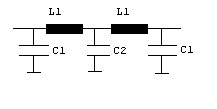
I have changed the lowpass filter. It is a half wave filter. Which means Xc = Xl =50 Ohm. I have used trimmers instead of fixed values.
Calculated values are:
Fc -3db = 178 MHz
C1 17p
L1 45nH
C2 34p
L1 has 3 turns, diameter 8 mm, length = 9 mm
I used 2 of those 5 pole filters.
I have used a 9 pole filter. The supression of harmoinics is much better now. It may not be enough though. Especially the third harmonic at 435 MHz seems to be too strong. The output and efficiency of the PA have increased whith this new filter.
So I think the spectrum analyzer gets overloaded. While alligning the harmonics change but the 145 MHz signal stays the same. I'll change the attenuator to get a lower level. That should help.
My handheld shows the same bad suppression of harmonics. That is another reason I think that the spectrum analyzer is overloaded.
I bought an step attenuator at ebay. It would be usefull for this measurement. Unfortuately it has not arrived yet.
Wednesday, May 19, 2010
Spurious 2
My new spectrum analyzer shows the same spurious signal levels the PRC-100 does. So they are real.
I got rid of one of the strong spurious signals. It was caused by oscillation.
I checked the output of the PLL. It shows two strong -15 db signals. One 2 MHz below carrier and one 2 MHz above the carrier. This explains some of the spurious in the output. I have no idea why the PLL generates those signals. Maybe the VCO is somehow modulated (AM of FM) by one of the digital signals.
The harmonic are too strong even though I use a 10 element filter. I have checked the component values. They are OK. I will change the filter into a half wave filter and improve the layout of the components. If this does not help then I will use different capacitors. Capacitors may behave as a inductor at high frequencies.
A different problem is the PSU. The transformer can not deliver the current needed for 5 watt output. In fact it can deliver it but it gets too hot and voltage drops too much.
Tuesday, May 18, 2010
Too much spurious signals
Last night I checked the spectrum using the icom prc-100. The results are not good.
Harmonics are only -35dbc. That is totally unacceptable. Some other spurious signals between 140 and 150MHz are present. They are -50dbc. That is not good enough.
The maximum level of a spurious signal is -60dbc.
Some of the signals may have been generated by the PRC-100 itself. I'll check the spectrum again using my new analyzer. However, I belief the harmonics are much too strong. I will check the low pass filter.
Some realignment could reduce some of the spurious around 145 MHz. I could add another bandpass filter if realignment does not help.
Monday, May 17, 2010
Status
This project has been on hold quite some time. Now it is time to continue.
My spectrum analyzer is almost ready. In fact in this state of the project it can be used to check the signal quality of the TRX. A few months ago I bought a icom PRC100 on ebeay. It is a computer controlled receiver. This radio has spectum analyzer functionality. I will use both to check the TRX.
For this test I made an attenuator to bring the signal down to levels the spectrum monitors can handle. The TRX is connected via the attenuator to a dummyload. The attenuated signal is fed to the analyszer.
I think a really need to get a CTCSS module because all repeates accessable to me use it. Personally I prefer simplex. However Activity on 2 meter is very low. Most activity is on the repeaters so I need to be able to use them.
Wednesday, July 22, 2009
FM modulator block diagram
This is the block diagram of the FM modulator.
The signal from the microphone is amplified. Then the signal is clipped and filtered.
After that it is used to modulate a super VXO at 10.7 MHz. The signal out of the super VXO is buffered and filtered.
The signal from the microphone is amplified. Then the signal is clipped and filtered.
After that it is used to modulate a super VXO at 10.7 MHz. The signal out of the super VXO is buffered and filtered.
 It took some effort to get enough deviation. Getting deviation was not that difficult. It was difficult to get enough deviation and a accurate carrier frequency. I managed to achieve this by used 2 varicaps parallel. The resulting FM sounds alright on a HF receiver tuned at 10.7 MHz.
Abandoned concept:
I tried a different modulator first. I made a PLL at 10.7 MHz using a 74??4046. This chip contains a VCO and a phase detector. FM was made by modulating the loop. It worded but it sounded awful. I found out that the PLL locked when the loop was open. It had a small catch area. Due to some internal coupling I guess.So I used a second a 74??4046 as VCO. It worked. The FM sounded excellent. However I could not make enough deviation without adding a lot of distortion. I don't know why. I think the concept is good the implementation must be wrong. Maybe the phase detector switches to frequency detector mode for high deviations. I stopped working at it as it would take too much time to figure it out. If I had succeeded I would have had a HiFi modulator. This would be overkill for a communication transceiver anyway . So I built a modulator using a VXO.
Tuesday, June 30, 2009
transmitter block diagram
This diagram shows the transmitter section.
It is straight forward. The mixer mixes the signal from the synthesizer with the 10.7 MHz signal from the FM modulator. The result is a 144 MHz signal. This signal is filtered and amplified. I have used several band filters to remove unwanted mix products. Finally the signal is amplified by a power module to 5 Watt. I have cascaded 2 low pass filters to get rid of the harmonics.
Tests with a spectrum analyzer have to be performed to check if the filtering is OK.
Friday, June 12, 2009
block diagram receiver

The receiver design is straightforward. See picture.
Only the squelch circuit is special. The NE604 has a mute input. I made a comparator with discrete components. The comparator checks the level output with the squelch threshold. If the signal is below the threshold the mute is activated.
This receiver had been build a few years ago. It did work but I was not satisfied. It had no squelch, the demodulated signal was weak, it had no preamplifier. The mixer was a BF960. I improved all those issues. Now it works fine.
The preamplifier is a mosfet with a tuned circuit at the gate and one at the drain. It has an issue. When both the input filter as the output filter are peaked at maximum the preamplifier oscillates. So it t needs a small misalignment.
The input is shielded form the output but that does not solve the problem completely.
Tuesday, June 2, 2009
block diagram PLL

This picture shows the PLL synthesizer. The concept is straight forward.
The VCO signal is mixed with the 132,3 MHz signal from the tripler.
This produces a signal between 1 and 3 MHz. The 4049 programmable divider can handle these frequencies. Phase detection is done by a 4046 phase detector. The reference signal 12.5 KHz comes from a 4060 (f/64) followed by a 74194 divider (f/5).
I have build this synthesizer years ago. The plan was to use it in a transceiver once. So it uses some older ic's. Back then I had some recent experience with these components so used them. If I had to do it again I would use modern components.
I improved several parts of the PLL. For example the step size. It used to be 25 KHz steps.
Subscribe to:
Posts (Atom)