The LCD has a build in led. I thought it was broken but isn't.
On the diode tester I could not measure it though.
It just needs a very smal resistor (33 Ohm) in series. not a 1 K ressitor.
Now I have light. It sure looks nice.
I have tested the switching power supply again. A 7809 an a few capacitors were used to clean the signal. The output looks clean however the transceiver produces too much spurious. I suppose the switching signal is coupled magnetically to some parts of the TRX. Anyway I can get 3 watts output power with the current PSU. That must be enough to drive an external amplifier.
Monday, May 31, 2010
Thursday, May 27, 2010
QSOs
The suppression of harmonics and other spurious signals seems to be adequate so I did a few on air tests. I had to realign the lowpass filter a bit because the 2nd harmonic was too strong when the antenna was connected.
After that I used it in a weekly radio meeting. Reports I got were ok. The modulation is ok for narrowband FM. In FM 'normal' the modulation is not loud.
Besides that the high tones may need amplification.
Power output is now 2 Watt. It can make 6 watts using a separate power supply. I have a powersupply that fits but it produces too much spurious.
Tuesday, May 25, 2010
pll spurious
The pll produces a signal between 133.3 and 135.3 MHz.This signal had some spurious 2MHz away from the carrier. I found out that it was caused by a 132.3 MHz signal. This signal leaked to the vco via the power lines.
I fixed this. Now I don't see any spurious around the carrier.So it is attenuated at least 60 db.
132.3 MHz is used to downmix the vco signal from 133.3-135.3 to 1-3 MHz.
I fixed this. Now I don't see any spurious around the carrier.So it is attenuated at least 60 db.
132.3 MHz is used to downmix the vco signal from 133.3-135.3 to 1-3 MHz.
Thursday, May 20, 2010
Harmonics 2
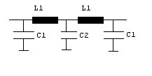
I have changed the lowpass filter. It is a half wave filter. Which means Xc = Xl =50 Ohm. I have used trimmers instead of fixed values.
Calculated values are:
Fc -3db = 178 MHz
C1 17p
L1 45nH
C2 34p
L1 has 3 turns, diameter 8 mm, length = 9 mm
I used 2 of those 5 pole filters.
I have used a 9 pole filter. The supression of harmoinics is much better now. It may not be enough though. Especially the third harmonic at 435 MHz seems to be too strong. The output and efficiency of the PA have increased whith this new filter.
So I think the spectrum analyzer gets overloaded. While alligning the harmonics change but the 145 MHz signal stays the same. I'll change the attenuator to get a lower level. That should help.
My handheld shows the same bad suppression of harmonics. That is another reason I think that the spectrum analyzer is overloaded.
I bought an step attenuator at ebay. It would be usefull for this measurement. Unfortuately it has not arrived yet.
Wednesday, May 19, 2010
Spurious 2
My new spectrum analyzer shows the same spurious signal levels the PRC-100 does. So they are real.
I got rid of one of the strong spurious signals. It was caused by oscillation.
I checked the output of the PLL. It shows two strong -15 db signals. One 2 MHz below carrier and one 2 MHz above the carrier. This explains some of the spurious in the output. I have no idea why the PLL generates those signals. Maybe the VCO is somehow modulated (AM of FM) by one of the digital signals.
The harmonic are too strong even though I use a 10 element filter. I have checked the component values. They are OK. I will change the filter into a half wave filter and improve the layout of the components. If this does not help then I will use different capacitors. Capacitors may behave as a inductor at high frequencies.
A different problem is the PSU. The transformer can not deliver the current needed for 5 watt output. In fact it can deliver it but it gets too hot and voltage drops too much.
Tuesday, May 18, 2010
Too much spurious signals
Last night I checked the spectrum using the icom prc-100. The results are not good.
Harmonics are only -35dbc. That is totally unacceptable. Some other spurious signals between 140 and 150MHz are present. They are -50dbc. That is not good enough.
The maximum level of a spurious signal is -60dbc.
Some of the signals may have been generated by the PRC-100 itself. I'll check the spectrum again using my new analyzer. However, I belief the harmonics are much too strong. I will check the low pass filter.
Some realignment could reduce some of the spurious around 145 MHz. I could add another bandpass filter if realignment does not help.
Monday, May 17, 2010
Status
This project has been on hold quite some time. Now it is time to continue.
My spectrum analyzer is almost ready. In fact in this state of the project it can be used to check the signal quality of the TRX. A few months ago I bought a icom PRC100 on ebeay. It is a computer controlled receiver. This radio has spectum analyzer functionality. I will use both to check the TRX.
For this test I made an attenuator to bring the signal down to levels the spectrum monitors can handle. The TRX is connected via the attenuator to a dummyload. The attenuated signal is fed to the analyszer.
I think a really need to get a CTCSS module because all repeates accessable to me use it. Personally I prefer simplex. However Activity on 2 meter is very low. Most activity is on the repeaters so I need to be able to use them.
Subscribe to:
Posts (Atom)